Every control engineering graduate has to show off by building a self-balancing
robot for some reason.
I’m a part of this clique, so I had no choice.
This robot usually manifests itself as a two-wheeled device that keeps itself
upright automatically by moving in the same direction it’s falling.
Imagine balancing a broomstick on your palm or a Segway.
I’ve attempted 5 different designs since 2018 and now, after over 7 years, I can
confidently say that the last one is quite good, and it was worth it, I guess.
I decided to compile the mistakes I made along the way and my solutions, so
other miserable control engineering students can finally get it over with.
Let’s start with the proof to earn your trust.
The robot’s main parts are the stepper motors,
an inertial measurement unit (IMU), an AVR microcontroller and a Li-ion
battery pack.
The microcontroller runs a cascade PID controller.
The outer loop controls the inclination and the outer one – the linear
velocity of the robot.
The inclination angle is measured by the IMU and cleaned up with a complementary
filter.
The robot can be controlled with a gamepad via Bluetooth both while balancing
and in horizontal mode.
Browse to the source code repository to get the schematics, CAD models, bill
of materials and, of course, the source code.
Now let’s proceed to the problems and solutions.
Making it too heavy, especially at the top
When you look for hobby balancing robots on the internet you’ll notice that most
of them are tall and have the batteries placed high up.
Their authors all seem to justify it by
bringing
up
the
same
argument
that increasing the relevant moment of inertia decreases the angular acceleration
caused by a force, which in the case of gravity slows down the falling.
That makes sense, but it may not exactly be what you want.
Making the moment of inertia high also increases the motors’ torque needed to
achieve a desired angular acceleration.
Top-heavy robots will be more sluggish than others, and they need beefier
motors.
If you
dig
deeper
you’ll notice that the most agile robots have their weight distributed lower.
A
few
commenters
on the Internet also came to the same conclusion.
My eureka moment was when I noticed that MiniRyś by KNR Bionik lifts
a bit when accelerating (or decelerating, depending on the direction) in
horizontal mode.
That gave me a hint that it must have a low moment of inertia.
I wanted to control my robot with a gamepad while it’s balancing, and I wanted it
to be fast and maneuverable.
That’s why I decided to make it short and place the heavy batteries low, between
the motors.
The current chassis is 16.5 cm tall with the batteries under the axle.
This one is very stable, fast and is able to stand up by itself.
While I was shortening the robot, I also tried to make it lighter.
I stripped out the unnecessary bits and replaced heavy materials with lighter ones.
I 3D-printed the chassis with a low infill value – 15%.
To make it stronger i increased the perimeter.
My robot now weighs only 1003 g.
Thanks to the lightness it responds quickly, is stable, mobile, the battery
life is longer, and the inevitable collisions are less dramatic.
To demonstrate the instability and sluggishness of top-heavy robots I fastened
a heavy metal egg (why do I own one?) to the robot using a long threaded rod.
Then, I used the gamepad to drive it around a little.
The experiment ended quickly and spectacularly.
Underestimating the sampling process
Before I read PID Without a PhD by Tim Wescott I thought that, within reason,
the higher the sample rate the better.
Forum
posts
didn’t help either, claiming you need around 1 kHz to balance such a robot
well.
This was not true in my case.
I had problems with high-frequency oscillations and parameter tuning until I
randomly decided to try halving my sample rate to 400 Hz.
It worked like a charm.
The noise in my derivative term decreased by a lot so I could crank it.
The oscillations were gone, and the robot started to balance way more smoothly.
A quote from the book sums it up well. “You should treat the sampling rate as
a flexible quantity.”
Another sampling mistake I made was neglecting the delay between the angle
measurement and the motor frequency update.
At first, I also didn’t configure the IMU’s output data rate so it used the
default of 100 Hz and the control loop frequency was 800 Hz.
This introduced a lot of delay, which PID controllers don’t like.
Also, the microcontroller was triggering a read after updating the controller
rather than before, which caused an additional delay.
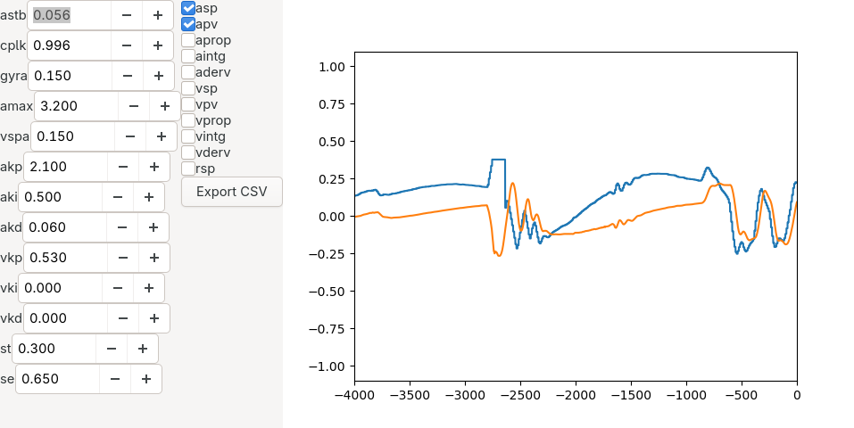
Not examining the signals early
Without the ability to examine the signals related to the controllers it was
very hard for me to diagnose regulation problems.
Being able to see the angles, velocities, errors, setpoints, control efforts is
indispensable, especially if you can do it live.
Having almost no experience with GTK, I’ve whipped up a terrible GUI that
could plot variables received via Bluetooth and change the controller parameters.
The first problem I caught with this setup was that the gyro range I’ve set was
too small, and it was saturating.
Now my accelerometer range is +-2g and +-500 deg/s for the gyro.
Another one was the gyro offset, which I overlooked.
It prevented me from setting the complementary filter’s parameter (gyro weight)
to a high value without causing a tug of war between both sensors.
Fortunately, the IMU chip has something called fast offset compensation, so
I could remove the offset by lying the robot down and running the procedure.
The last one was the noise.
The complementary filter got rid of most of the accelerometer noise, but there
was a lot of high frequency noise in the gyro readings.
In my case, adding a simple low-pass IIR filter for just the gyro almost eliminated it
and improved the stability by a lot.
Causing glitches in step signals
To drive stepper motors, we must generate STEP signals for each motor.
When the motor driver detects a rising edge on the STEP pin, it performs
a single (micro)step and the motor’s shaft turns a tiny amount.
Unfortunately, there is one small problem with generating variable frequency
square waves using digital counters.
The ATmega328PB datasheet sums it up pretty well.
Changing [the counter’s maximum value] to a value close to [0] while the
counter is running must be done with care […].
If the new value written to [the output compare register] is lower than the
current value of [the counter], [it] will miss the compare match.
The counter will then count to its maximum value [0xFFFF] and wrap around
starting at [0] before the compare match will occur.
To fix that, we can enable the PWM mode, which provides double buffering of
the output compare register.
But that introduces another problem.
If we set the counter’s frequency to a very low value, let’s say 0.1 Hz, we
cannot generate another edge on the output until the counter counts to the
maximum value, which in this case takes 10 seconds.
This means that setting that low of a frequency will essentialy freeze the motor
for the duration of one counter cycle.
My simple and effective solution to this problem is to set a lower bound on the
frequency.
This happens naturally by setting the counter frequency to the highest possible
value (prescaler disabled).
With the system clock set to 20 MHz, the minimum STEP signal frequency is
20 MHz / 2 / 65536 which is around 150 Hz.
This might sound like a big jump from 0 to 150 Hz, but I didn’t notice any
problems caused by that in practice, probably thanks to 1/32 microstepping.
Another cause of glitches in my STEP signals was updating counter registers
in a wrong order.
When I changed the stepper motor drivers from DRV8825 to TMC2209 the robot
started to jerk once every couple of seconds while balancing.
It seems that the new drivers were less tolerant to glitches and I had to fix
them.
Making sure that the direction outputs are updated before the output compare
registers eliminated the perceivable glitches entirely.
Making step changes to the velocity setpoint
It was impossible to control the robot when I mapped the velocity setpoint
directly to the position of one of the gamepad’s joysticks.
The abrupt changes to the velocity setpoint caused the robot to oscillate and
fall over every time I touched the joystick.
Low-pass filtering the setpoint (like the gyro) fixed this problem.
While I was at it, I applied an identical filter to the angular speed for the
controls to be consistent.
Underestimating the balance point
My robot’s center of mass is not directly above the axle.
It has been way easier to tune the regulators since I’ve taken it into account.
I found an angle setpoint that made my robot balance in place with zero
linear velocity.
I disabled the outer (velocity) PID while leaving the inner (angle) one on.
This way, imbalance was easier to spot as the smallest deflection caused the
robot to quickly accelerate.
When I found the angle, I slowly increased and decreased it to find
a range of stable setpoints.
I then placed my setpoint right in the middle of this range to get a more
precise value.
Even small changes in the construction of the robot influence the balance point,
so I repeated this procedure after every change to the chassis.
Trying to use UART synchronously on Linux
My first implementation of the telemetry module was bad.
There was a special UART command telem that responded with telemetry data.
This made the PC-side implementation simple.
Send telem command, wait for response, parse it, send another telem command and so on.
Synchronous and simple.
Apparently such an approach makes it very slow on Linux.
I got a throughput of 2.5 kbps which was only 63 samples per second.
My control loop executed 400 times a second, so there was no chance of recording
data after every iteration.
Setting the low_latency serial port flag helped a lot (28 kbps, 700 sps).
Ultimately, redesigning telemetry so that it just sends data without waiting for
a command was the way to go.
Now the bottleneck is the robot’s processor time, which is how it should have
been from the beginning.
Trying to use fixed-point math
My computer architecture lecturer, Grzegorz Mazur, said that when one thinks
about using floating-point operations, they should reconsider.
If you don’t NEED floating-point, use fixed-point, he said.
Well, either I’m wrong (likely) or he’s wrong (unlikely) because I couldn’t make
my control loop faster using fixed-point ops to save my life.
My best attempt was 1040 us (fixed) vs 757 us (float), measured by connecting
an oscilloscope to a pin and toggling it when entering and exiting the controller
update routine.
I used the sat accum (Q16.16) type everywhere, to eliminate conversions, but
it was no use.
It may be because I kept the floating-point atan routine.
Was my implementation that bad or are floating-point operations that well
optimized on AVR?
That I don’t know, but I don’t think it’s worth it to explore this now.
With floats, the robot’s microcontroller still has a bit of time for tasks other
than updating the controllers, like processing commands and sending telemetry.
Not limiting acceleration
With steppers, I overlooked the fact that while I can change the frequency of
the step signal arbitrarily that doesn’t mean that the motor will always
obediently perform the steps.
My robot currently doesn’t have wheel encoders, so there’s no wheel position
feedback.
Limiting the acceleration helped a lot with a smooth transition from horizontal
mode to balancing.
One exception, where I allow high acceleration is breaking.
This makes it possible for the robot to use its momentum to stand up.
I’m happy with the current design of my self-balancing robot.
It’s so much fun to play with not only by myself, but controlling it is so easy
it makes for a great activity when I have people over.
If you are a control engineering graduate, I hope this article helps you to free
yourself from the self-balancing robot hell.
If you are a regular person, I hope it inspires you to try building one.
Now it’s time for me to shelve this project for another seven years.
But before I do that, here’s one last video showing how the robot changed since
I started this project.