The idea of an LED lamp with smooth control of hue, saturation and brightness
was floating around in my head for quite a while now.
I knew I finally had to make one when I found an old ceiling light with a large
conical frosted glass cover.
[Source code]
[Schematic and PCB layout]
[3D models]
The enclosure is 3D printed.
The top transparent part acts as a light diffuser.
Inside there is a 3 W RGB LED.
The bottom part houses the electronics.
The front panel features an on-off switch and three knobs, which
control the hue, saturation and brightness of the light.
On the back there is a barrel jack socket to connect a 12 V power supply.
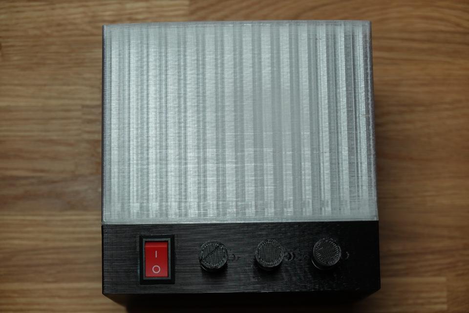
Front panel
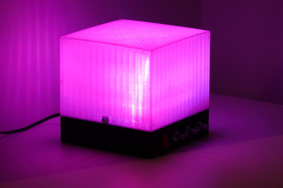
For its size, the lamp is surprisingly bright.
First prototype
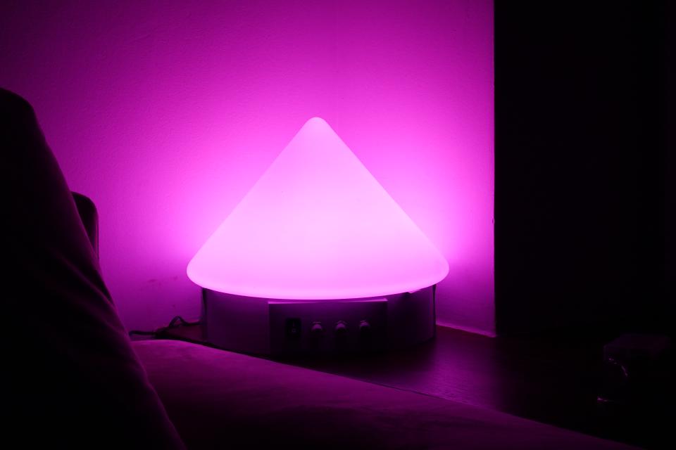
First prototype. Conical part reused from a ceiling light.
The first iteration of the project was a single prototype that uses the cover
for an old ceiling light as a diffuser.
The conical glass part sits on top of a 3D printed base, which also
provides some space for the front panel.
Of course this is not a sustainable way to create more lamps.
This is why I designed a smaller, wholly 3D-printable enclosure.
The prototype also has three 3 W LEDs which makes it a 9 W lamp.
It also has a hue knob with continuous rotation (see section: Issues).
The prototype’s frosted glass cover diffuses the light way better than the
transparent 3D printed plastic, but I only had one of those.
Theory of operation
The three knobs set the coordinates in the
HSV color space.
These coordinates are translated to RGB and respective LED channels are driven
with power proportional to the R, G, and B coordinates.
This process is performed by a microcontroller in a loop.
First, the position of all knobs is read by the built-in 10-bit
ADC.
Then, the knob positions are mapped to the correct ranges, which is 0.0 - 360.0
degrees for hue and 0.0 - 1.0 for saturation and brightness.
Next, these formulas are used to convert HSV coordinates to RGB.
Finally, RGB coordinates (range 0.0 - 1.0) are mapped to 8-bit integers (range
0 - 255) and duty cycle of respective
PWM channels is set to these values.
The PCB
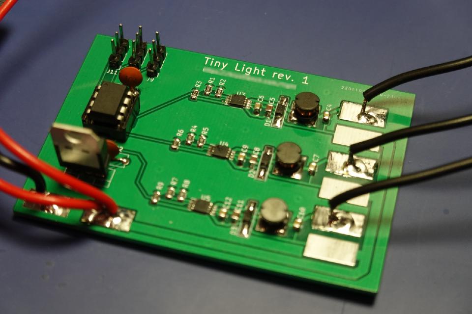
The PCB
The main PCB features a three channel LED driver based on the LM3407
IC, an ATtiny85 microcontroller,
a 7805 linear voltage regulator, bypass capacitors, pin headers and pads for
soldering wires.
The circuit and layout of the LED driver channels is taken straight from the
LM3407 datasheet.
The LED current is set for each channel by parallel resistor pairs R1&R2, R4&R5,
R7&R8.
The resistor pairs are 1 and 1.5 Ohms so the parallel configuration yields 0.6
Ohm equivalent resistance.
The formula for calculating the set current is 0.198 V divided by the equivalent
resistance of the sense resistors, which in this case is 330 mA.
The maximum rated constant current is 370 mA, so the LEDs are underdriven to
extend their lifetime.
Cooling
When it comes to LEDs, cooling can’t be disregarded.
High-power ones get hot quick and with inadequate cooling they die soon after
that.
In order to ensure a long life of the lamp I had to make sure that all the heat
can be safely dissipated.
In the original large 9 W prototype the cooling solution is basically built-in.
LEDs are soldered to an aluminum PCB, which is fastened to the metal
base of the ceiling light.
This dissipates heat so well that the LEDs stay very cool.
However, the second iteration only had a small aluminum PCB with nothing
heat-conductive to mount it to.
Fortunately, there were some flat aluminum profiles in my dad’s scrap metal bin.
He cut it for me into several 60 x 60 x 5 mm plates.
I could then glue the PCBs to the plates with a thermally conductive adhesive
ensuring good heat dissipation.
The manufacturers of such LEDs recommend that the temperature of the LED
enclosure should stay below 80 degrees C.
With this heat dissipation solution the greatest temperature I recorded was 62
degrees with a 21 degree ambient temperature, measured with a thermocouple.
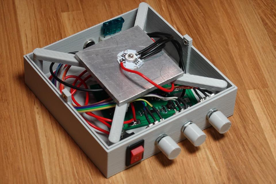
Internals. Diffuser removed.
Issues
The first issue became apparent very quickly after running the first version of
the program.
The potentiometer with continuous rotation has an issue of being scratchy on
boundaries of the open section.
What I mean is that there are two very narrow ranges of angles where the
resistance between the wiper and the lugs change very quickly and unpredictably.
In practice this meant that there were very short but noticeable flashes of blue
light while rotating the hue knob near +/- 5 degrees.

Visualization of continuous potentiometer’s range. Linear section in blue. Open section in gray. Scratchy sections in red.
The next issue is the lack of calibration.
Due to the different luminous flux per milliamp of current for each of the LED
channels, the hue, saturation and brightness controls are not fully independent.
For example, the hue and saturation of the light also change a little when
turning the brightness knob.
This effect is most noticeable when brightness is low.
A possible solution would be to compensate for this effect, but that would call
for some kind of color calibration tool and I haven’t looked into that yet.
Maybe a DSLR would be
enough.
8-bit PWM allows setting only 256 distinct power levels to the LED channels.
Levels below 11 cause flickering because they provide barely enough power to
light up the LEDs.
This leaves us with 245 power levels.
Unfortunately this is not enough to prevent a stepping effect while slowly
rotating the knobs.
A microcontroller with a 16-bit PWM channel would solve this problem.
When designing the PCB I thought I won’t need a programming connector because
I can always pull out the microcontroller from the socket and put it into a
breadboard set up for programming.
However, the constant pulling the chip in and out of the socket turned out to be
very inconvenient during development.
I’d also want to include a fuse holder or a polyfuse on the next revision of the
PCB so that I won’t have to mount an external fuse in the enclosure.
I also didn’t think much about connecting the power wires to the PCB and the
large soldering pads is not a good solution for this.
Next time I’ll probably just use through-holes.
The 3D-printed enclosure also needs some more attention.
While the thick frosted glass of the first prototype diffuses the light
beautifully, the transparent
PETG plastic
doesn’t.
Even a 3 mm thick layer of it refracts light in such a way that the primary
colors peek through, especially in the lower part that is closest to the LEDs
inside.
I’ve experimented with various levels of infill for the prints to mitigate this
effect.
However, both values I tried had some downsides.
15% infill causes vertical stripes to be visible when light shines though the
part.
100% infill gives a sparkly lattice on the top side of the cube and still doesn’t
completely get rid of the refraction effect.
Other things I’d like to try in the future are different infill patterns,
even more thickness on the transparent part and printing an additional inner
diffuser.
Summary
I wanted to own such a lamp for a long time.
The smooth control of the hue is very satisfying.
Despite many issues with the design, it’s very functional.
My partner and I use it a lot.
We placed the large 9 W one in the corner of the living room, where it
lights up the walls beautifully.
After eight months, my partner still turns it on and chooses a different color
almost every evening.
She also put one of the 3 W lamps on her desk and turns it on when the sun starts
to set.
I’ve also given one as a gift for Christmas and the feedback was very positive.